Ground Plane Antenna: How to Build and Tune a Quarter-Wave Vertical
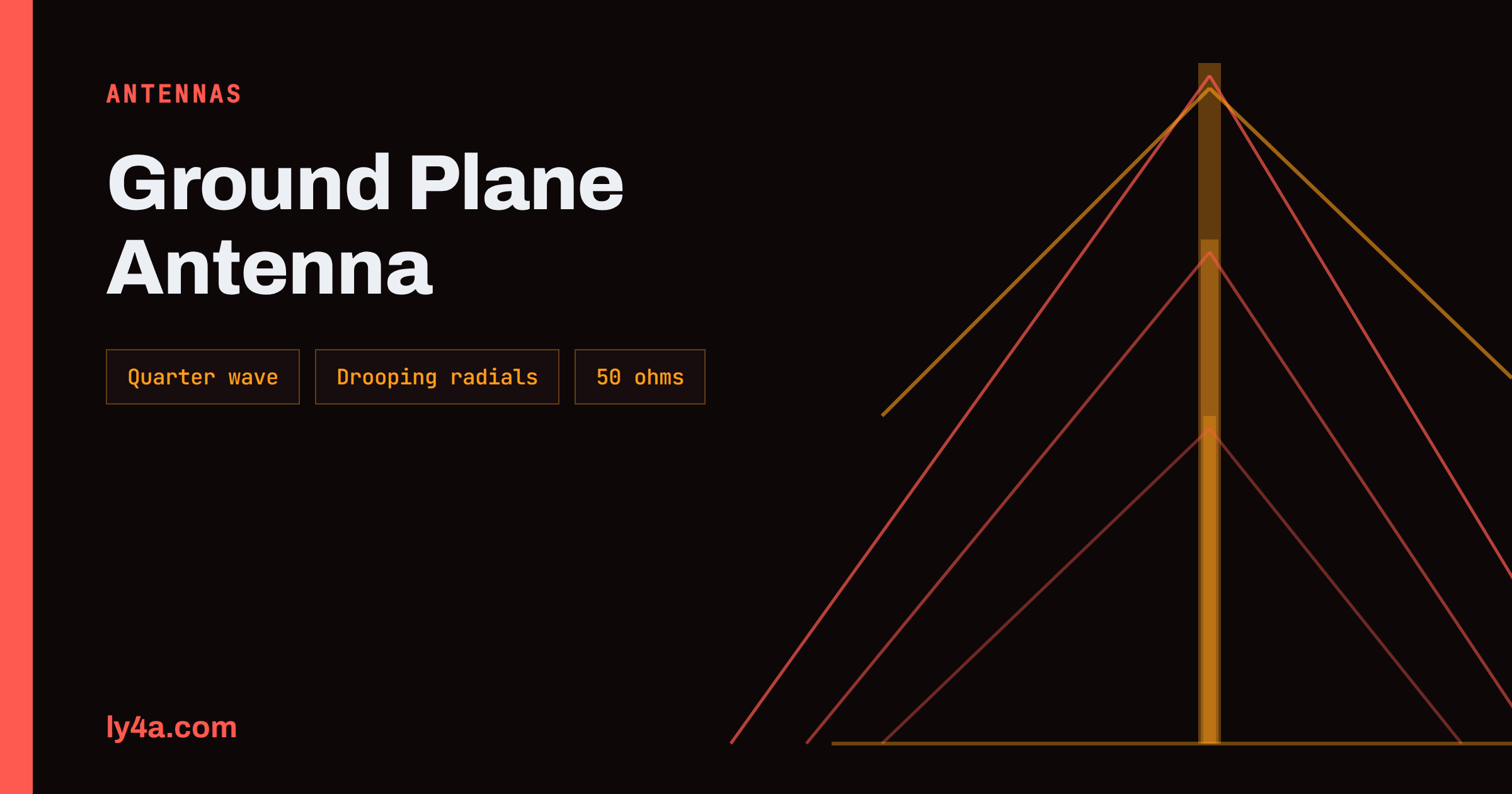
The ground plane antenna is one of the oldest and most popular designs in amateur radio. It is a vertical radiator, one quarter of a wavelength long, standing over a set of horizontal or sloping wires that stand in for the earth. It costs little, it can be made in an afternoon from a connector and a few pieces of brazing rod or wire, it has a low angle of radiation and it matches a 50 ohm cable with no matching network if the radials are set correctly. For VHF and UHF it is an excellent first antenna, and for 10 and 6 meters it makes a good omnidirectional antenna on a mast. This guide explains how a ground plane antenna works, how the angle of the radials changes the impedance, how to calculate the dimensions, how to build and tune one and how to avoid the common errors of feedline radiation and a poor mounting position.
How the Antenna Works
A half-wave dipole has two equal arms, and the current flows from one to the other. If you take one arm and replace the other by a conducting surface, the surface acts as a mirror, and the image of the single arm supplies the missing half. This is the principle of the monopole antenna, and the ground plane antenna is its practical form. The radiator is a vertical rod of a quarter wavelength, and the mirror is made by several radials that extend from the base. The radials carry the return current of the antenna, and for that reason they are not a decoration.
The antenna is fed at the base. The centre conductor of the coax goes to the vertical element and the braid goes to the radials. Because the vertical element is a half-wave dipole in a mirror, the pattern in the horizontal plane is a circle: the antenna radiates equally in all directions around it. In the vertical plane the energy goes out at a low angle, with a null straight up, which is exactly what is wanted for local contacts, repeaters and the VHF bands in general. The Wikipedia entry on the ground plane antenna describes the basic design with its radials.
Radial Angle and Impedance
The impedance at the feedpoint depends on the angle of the radials. With the radials horizontal the impedance is about 36 ohms, a value that gives an SWR of about 1.4 on a 50 ohm cable. If the radials droop downward, away from the vertical element, the impedance rises. At an angle of about 45 degrees below the horizontal it comes close to 50 ohms, which is the ideal match for coax, and the radials continue to raise the value until, if they pointed straight down, the antenna would become a vertical dipole with a feedpoint impedance of roughly 70 ohms. The figures below are typical values; the real number depends on the diameter of the rod and the height.
| Radial angle below horizontal | Approximate feedpoint impedance | SWR on 50 ohm coax |
|---|---|---|
| 0 degrees (horizontal) | 36 ohms | about 1.4 |
| 30 degrees | about 45 ohms | about 1.1 |
| 45 degrees | about 50 ohms | about 1.0 |
| 60 degrees | about 60 ohms | about 1.2 |
| 90 degrees (vertical dipole) | about 70 ohms | about 1.4 |
Drooping the radials has a second advantage: it lowers the angle of the pattern a little and reduces the current on the outside of the cable, because the radials act as a better screen. Builders therefore choose an angle of 30 to 45 degrees for a simple antenna. A fixed horizontal arrangement is equally possible when the match of 1.4 is acceptable or when a matching section is used.
Cutting the Elements
The length of a quarter wavelength in free space is 300 divided by the frequency in megahertz, divided by four, in metres, or 75 divided by the frequency. The real length of the element is somewhat shorter, because the thickness of the rod and the end effect lower the resonant frequency. A practical rule is to use 95 percent of the free-space value, which gives 71.3 divided by the frequency for the vertical element in metres. Make the radials about 5 percent longer than the vertical, because they do not need to be resonant and should not be shorter than the element. The idea of cutting a little long and trimming is the safest.
- 2 meters at 146 MHz: vertical about 49 cm, radials about 51 cm.
- 70 centimetres at 435 MHz: vertical about 16.4 cm, radials about 17 cm.
- 6 meters at 51 MHz: vertical about 1.40 m, radials about 1.47 m.
- 10 meters at 28.5 MHz: vertical about 2.50 m, radials about 2.63 m.
Start with these values and finish with an analyzer. The simple method is to make the vertical a centimetre or two longer than the formula and to cut it in small steps until the resonance falls at the desired frequency. Trimming from the long side is easy, and adding material to a short rod is difficult.
Building a 2 Meter Ground Plane
A simple version uses an SO-239 chassis socket, a piece of brazing rod of 3 or 4 mm for the vertical, four rods or stiff wires for the radials and a small mounting plate. The vertical is soldered to the centre pin of the socket, and the four radials are fixed to the flange, through the mounting holes or soldered to a ring of metal. The construction is mechanical rather than electrical, and the main issue is that the joints are strong and sealed against the weather. Four radials are the usual number, with 90 degrees between them, bent down by about 45 degrees. Three radials are also acceptable, but four give a more even pattern.
Use a good quality connector and seal it, as explained in the guide to weatherproof coax connectors. Rain that enters the socket changes the match and corrodes the contacts, and an antenna that is perfect on the bench can be poor after one season. The same applies to the rod: a stainless steel or brass rod lasts longer than a bare mild steel one, and aluminium tube is lighter for a long element on 10 meters.
Tuning With an Analyzer
Connect an antenna analyzer or a NanoVNA at the end of a short piece of cable, with the antenna in the clear and at a height of at least a couple of metres above the ground. Sweep the band and find the frequency at which the SWR is lowest. If the dip is below the desired frequency, the vertical is too long, and you should trim it by a small amount. If the dip is above, the vertical is too short. The radials affect the result less, but their angle sets the impedance, so you may need to bend them a few degrees up or down to bring the minimum SWR near 1.0. Calibrate the instrument at the end of the cable before the sweep. Remember that a measurement at a low height is affected by the objects near the antenna, so repeat the check at the final position and trim only a little.
Feedline Radiation and the Choke
The most common problem with a ground plane antenna is current on the outside of the coax. The vertical element is fed against the radials, but if the radials are not a good counterpoise, or if the feedline hangs vertically below the antenna, the braid becomes part of the antenna. The cable then radiates and picks up noise, and the pattern is distorted. The remedy is a choke at the feedpoint: several turns of the coax wound into a coil of about 15 to 20 cm in diameter, or a set of ferrite beads on the cable. The principle is explained in the article on common-mode chokes. It is a cheap part and it makes the antenna more predictable.
The drooping radials help here, because they present a symmetrical screen to the cable. Bring the cable away from the antenna at a right angle, or down behind the radials, and do not let it run vertically along the element or the mast.
Where to Mount It
An antenna that is working well on a table can give poor results on a roof. The best position is the highest point of a mast, with the vertical element above any other structure. A metal mast below the radials becomes part of the antenna if it is within the near field, and for that reason a metal pole is acceptable only if the radials are at least a quarter wavelength from other metal and if the pole is below them. A fibreglass or wooden pole above the metal is better. Keep the radials at least a quarter wavelength from walls, gutters and other antennas. Mounting height is important for the VHF bands, since the horizon depends on it, as our article on the radio horizon shows. A few extra metres of height are worth more than a few decibels of gain.
Variations and Limits
The quarter-wave ground plane is a good all-round design, but the family has relatives. The 5/8 wave vertical raises the gain by a decibel or two by using a longer element and a matching coil, and the J-pole replaces the radials with a half-wave stub that is easy to build from twin lead or tube, as described in the comparison of 2 meter antennas. For the HF bands the quarter-wave vertical is much larger, and it works best with many radials on or in the ground, in which case the need for a real counterpoise is more demanding than for VHF.
The limits of the antenna are also clear. It has no gain compared with a dipole in the horizontal plane, only a low angle of radiation, and its bandwidth is wide enough for a normal VHF band but not for a very wide range of frequencies. The polarization is vertical, which matches the mobile and handheld stations on FM, but it will not suit the weak signal work in the SSB segments that uses horizontal polarization. The choice between the two is discussed in our guide to vertical and horizontal polarization.
Common Mistakes to Avoid
A few errors appear again and again on the antennas that come to the workshop of a club. The first is to make the radials too short or to use only one or two; the antenna then behaves like a poor dipole, and the pattern tilts toward the side with more wire. The second is to bend the radials upward, which lowers the impedance and raises the SWR, and which also changes the pattern. The third is to mount the antenna directly on a metal mast with no separation, so the mast becomes a part of the radiator and the resonance moves. The fourth is to forget the weatherproofing at the base, which is the most common cause of a good antenna becoming a bad one within a year. The fifth is to test the antenna in a room with metal furniture and then to fit it on the roof without checking again. Measure at the final location, with the cable in its final route, and keep a note of the readings. If the numbers change after a storm, a loose joint or a bent radial is the likely cause, and the note will help you to find it quickly.
The Bottom Line
A ground plane antenna is a quarter-wave vertical element over three or four radials. The radials act as the missing half of a dipole, and their angle sets the impedance: about 36 ohms when horizontal and about 50 ohms when they droop 45 degrees. Cut the vertical to about 71.3 divided by the frequency in MHz, in metres, make the radials a little longer and trim to resonance with an analyzer. Seal the connector, add a choke to stop current on the coax, and mount the antenna high and in the clear with the cable leaving at a right angle. It gives a simple, omnidirectional, low-angle antenna for VHF and UHF.
Frequently Asked Questions
How many radials does a ground plane antenna need?
Four is the normal number for a VHF or UHF ground plane, spaced 90 degrees apart. Three also work, and more than four add little on VHF.
Why do the radials droop downward?
Drooping them by about 45 degrees raises the feedpoint impedance from about 36 to about 50 ohms, which matches coax, and it also reduces current on the outside of the cable.
How long should the element be?
About 71.3 divided by the frequency in megahertz, in metres, for the vertical. For 146 MHz this is about 49 cm. Cut it a little long and trim it with an analyzer.
Does a ground plane antenna have gain?
Not much. It has a gain close to that of a dipole, with the energy at a low angle and equal in all horizontal directions, which is helpful for local and repeater contacts.
Do I need a choke on the coax?
It is recommended. A few turns of the coax or a few ferrite beads at the feedpoint reduce the current on the outside of the cable and keep the pattern clean.
Can I use a ground plane antenna on HF?
Yes, but on HF the quarter-wave vertical needs a much larger radial system. It is usually done with many wires on or in the ground, or with elevated tuned radials.