Sloper Antenna: One-Mast Wire Dipole for HF DX
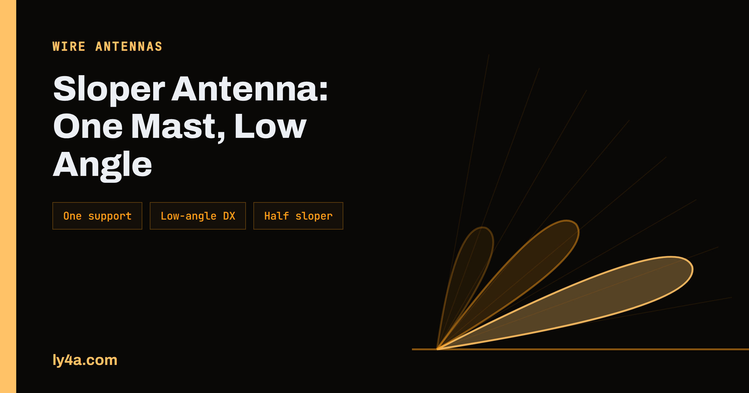
A flat horizontal dipole is a wonderful antenna if you have two tall supports at the right distance apart. Most people do not. A sloper antenna solves that problem by tilting the dipole so that one end is high on a single mast and the other end is low near the ground. The result is a one-support wire antenna that radiates at lower angles than a low flat dipole, which makes it a favourite for DX on the lower bands, and it is cheap, quick to build and easy to take down. This guide covers how it is built, what angles and heights work, how the feedline should be routed, how the half-sloper variant differs and where a sloper is a better choice than a dipole or an inverted V.
What a Sloper Is
The basic description in the sloper antenna reference is short: it is a slanted dipole antenna. A horizontal dipole needs two large support masts, while a sloper needs only one, which is why it is widely used by radio amateurs with limited space and is particularly interesting for the low frequencies. The angle of the slope is usually between 45 and 60 degrees, and the lower end of the wire should be at least a sixth of a wavelength above the electrical ground. It is typically fed with coax at the centre, at the top of the supporting mast, and because of its low-angle radiation pattern it performs well for long-distance contacts.
That description holds a few important ideas. First, the antenna is still a dipole at heart, with two legs and a centre feed point. Second, the tilt changes the pattern: instead of the clean figure-of-eight of a flat dipole, you get a pattern that favours the direction in which the wire slopes down. Third, the height of the low end is not an option. If it is too close to the ground, the antenna loses efficiency and the lower leg becomes a hazard for anyone walking beneath it.
If you are still choosing between basic antennas, our guide to a first HF antenna compares the dipole, the vertical and the end-fed wire, and explains why the dipole family is a good starting point.
Why Choose a Sloper
A sloper is chosen for practical reasons, and it has particular strengths on the lower bands.
- One support. A tower, a mast, a tall tree or the side of a building is enough. The low end can be tied to a stake, a fence or a short pole.
- Low angle of radiation. A sloper is partly vertical, so it radiates a good share of its power at low angles compared with a flat dipole at modest height. That is helpful for long-distance contacts on 40, 80 and 160 metres, where a full-height horizontal antenna is not practical. Our article on antenna height and takeoff angle explains why low angles matter for DX.
- Directional hint. The wire favours the direction towards which it slopes, and several slopers on one support can be arranged around the mast to cover different directions with a switch.
- Quick to deploy. For a field day, a contest expedition or a temporary operation, a sloper goes up fast and comes down just as fast.
The trade-off is that a sloper is not a perfect antenna. The pattern is somewhat irregular, nearby metal affects it more than it affects a flat dipole, and the lower leg needs space. You may also find that it has less gain in the direction opposite to the slope. But on a small plot it often beats the alternatives.
Dimensions, Angle and Height
The wire length starts from the same formula as an ordinary dipole: about 142.5 divided by the frequency in megahertz gives the total length in metres. For 3.6 MHz that is about 40 metres, and for 7.1 MHz it is about 20 metres. Because the wire droops and is near the mast, the resonant length is slightly different, so cut a little long and trim while you measure the standing wave ratio.
Two measurements decide how the sloper behaves: the angle of the wire and the height of the low end. The standard guidance gives a range of 45 to 60 degrees for the slope and a lower end at least a sixth of a wavelength above ground. The table below turns that into examples for a half-wave sloper at a 50 degree slope, assuming that the high end is at the top of the support. Figures are rounded.
| Band | Total wire length | Minimum low end height (1/6 wavelength) | Vertical drop along the wire at 50 degrees |
|---|---|---|---|
| 80 m (3.6 MHz) | about 40 m | about 14 m | about 31 m |
| 40 m (7.1 MHz) | about 20 m | about 7 m | about 15 m of vertical drop |
| 20 m (14.1 MHz) | about 10 m | about 3.5 m | about 7.7 m of vertical drop |
The figures show the real constraint. Honouring the one-sixth wavelength rule on 80 metres needs a very tall support, and most operators compromise by using a bent or shortened wire, a lower slope or a loaded design. On 40 and 20 metres, a sloper fits most masts and towers with ease. Where you cannot reach the minimum height, accept that the efficiency will be lower and keep the low end out of reach for safety.
Feedline Routing
The feedline has a larger effect on a sloper than on a flat dipole. The reference notes that at least a quarter wavelength of the feedline should leave the antenna at a right angle to the wire. If the coax runs along the wire or hangs close to it, current is induced on the outside of the shield, which distorts the pattern and brings RF into the station.
- Leave the feed point at 90 degrees. Route the coax away from the wire, and keep it away for as long as practical.
- Use a choke. A current choke at the feed point reduces the common-mode current. Our guide to baluns and ununs helps you choose between a balun and a choke.
- Do not run the coax down the mast in contact with the wire. If you have to run it along a tower, use a standoff and a choke.
- Weatherproof the feed point. A sloper hangs near the mast, so any water that enters the connector collects there.
It is also possible to feed a sloper asymmetrically, but for a first project the centre-fed version with a choke is the best-behaved.
The Half Sloper and Full Sloper
The word sloper covers two related designs. A full sloper is a complete dipole tilted at an angle, with both legs of the dipole made of wire and the coax connected at the centre. A half sloper uses only one leg: a quarter-wave wire runs from the feed point at the top of a metal tower down to a stake, and the tower itself acts as the other half of the antenna, with the coax shield connected to the tower and the centre conductor to the wire.
- Full sloper. More predictable, because it does not depend on the tower. It works well on a wooden pole, a mast or a tree, and it gives a lower SWR over a narrower bandwidth. It needs more wire.
- Half sloper. Needs a metal tower, usually one that is already part of the station. It uses less wire, but the results depend on the tower, its guys and the other antennas on it. A tower loaded with a beam can behave quite differently from an empty tower. Measure carefully and expect surprises.
The half sloper is popular on the low bands for contest stations with a tower, and large stations use a set of them around a tower to give switchable directions. If you do not have a tower, start with a full sloper. If you have a tower already, a half sloper is a cheap experiment, as long as you keep safety in mind.
Safety
A sloper’s low end is high-voltage when you transmit, and its high end is at the top of a support. Keep the low end out of reach of people, children and animals, and keep it well away from power lines and metal fences. Place the wire so that no one can trip over the stake or the rope, and mark it with a bright cord in the daytime. For a tower installation, tie the work to the tower’s safety rules, and do not climb a tower unless you are trained to do so. The ARRL and your national society publish guidance on RF exposure and tower work, and the dipole antenna reference explains why the voltage at the ends of a dipole is the highest point of the system.
Using Slopers on the Lower Bands
On 160 metres, slopers are a long-standing technique. The Wikipedia summary cites the sloper system at a well-known contest station as an example of the approach, and many operators use a set of slopers on a tall tower as a low-angle DX antenna. Our article on the 160 metre band explains why low angles and low noise matter on the top band. On 80 and 40 metres a sloper is a good compromise when a flat dipole is not possible, and on 20 metres a sloper can be practical on a modest mast.
Building and Tuning a Sloper Step by Step
A sloper is simple enough to build in an afternoon, and the sequence below avoids the usual mistakes.
- Choose the support and the direction. Decide which way you want the wire to slope. The low end points towards the direction you want to favour, so if you want to work a particular region, aim the lower end towards it.
- Cut the wire long. Use the length formula and add about five per cent. Keep both legs equal for a full sloper.
- Fit the feed point. Attach a centre insulator at the top, fit a choke on the coax within a short distance of it and take the coax away at a right angle.
- Raise the wire. Tie the upper end to the support using a strong rope and a proper insulator. Pull the lower end out to a stake and tie it to an insulator and a length of rope that you can adjust.
- Measure. Use an antenna analyser to find the resonant frequency. If it is too low, trim a little from each end, and if it is too high you have cut too much, so add a short extension.
- Check the whole band. Record the SWR at the bottom, middle and top of the band, and note the bandwidth. A narrow bandwidth is normal on the lowest bands.
- Test on air. Use a reporting network or a friendly station to compare the sloper with your existing antenna in several directions. The difference between directions may surprise you.
Keep notes. A sloper is sensitive to its surroundings, and a log of angle, height, wire length, measured resonance and results turns your experiments into a design you can repeat.
The Bottom Line
A sloper is a practical answer to a common problem: you need one tall support, a length of wire and a little patience. Keep the slope between about 45 and 60 degrees, keep the low end at least a sixth of a wavelength above the ground, route the feedline away at a right angle and add a choke. Choose a full sloper if you have a pole or tree, and a half sloper if you have a tower. Measure the result, trim the wire and keep the ends out of reach. That is all you need to get a low-angle antenna into the air without a second mast.
Frequently Asked Questions
What is a sloper antenna?
It is a slanted dipole antenna. One end is high on a single support, and the other end slopes down towards the ground, which makes it useful when you have only one tall mast or tree.
What angle should a sloper be?
Usually between 45 and 60 degrees. The lower end of the wire should be at least one sixth of a wavelength above the ground.
Does a sloper work better than a dipole?
It depends on the installation. A sloper radiates at lower angles than a low flat dipole, which helps for DX on the lower bands, but a high flat dipole is usually the better antenna if you can build it.
What is a half sloper?
A half sloper uses one quarter-wave wire fed against a metal tower, with the tower acting as the other half. It uses less wire than a full sloper, but its performance depends on the tower and anything mounted on it.
How should I route the coax on a sloper?
Leave the feed point at a right angle to the wire for about a quarter wavelength where possible, use a choke at the feed point and avoid running the coax along the wire.
Can I use a sloper on 80 meters?
Yes, but a full-size 80 metre sloper needs a tall support. Many operators use a shortened or loaded version, or accept a lower efficiency when they cannot reach the recommended height.